Working with the Encryption Box team we put together a script and storyboard to define the working of their forthcoming animated video production which when shown to the judges of the Digital Media Awards they would go on to win their section.
1st a script was written and agreed so that the client was happy. Click here to view the script . Once the script and storyboard were approved the actual animation production was produced under pressure within a week.
Storyboard for Animated Video Production
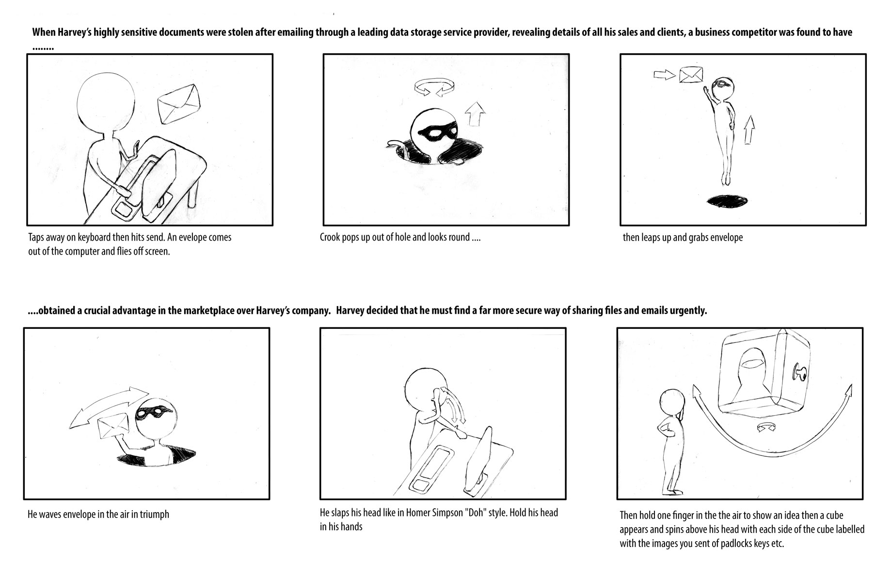
When the script was finalized we made an animation storyboard to fully define the series of events to be depicted. A section of which is above.
When this was fully agreed upon then the morph-type figure was rigged with a 3ds max biped. and animation began.
The rigging was checked by having the rigged 3ds max biped character studio figure’s skeleton move through a range of motion as in the video below using this file click here (originally made and distributed by Paul Hormis as part of his excellent now discontinued HyperRigger biped rigging and skinning script).
Each section of the animation was submitted for approval before final rendering:
Once approved each section was rendered in turn whilst animating the next section.
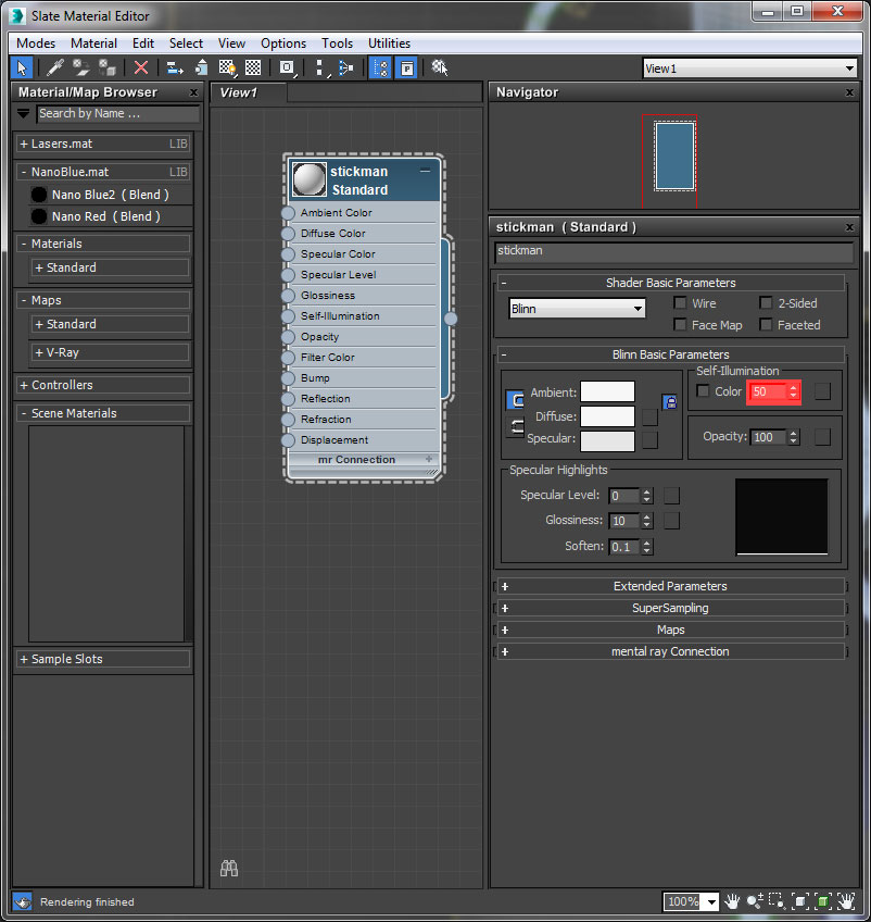
The look of the animation is partly that the material on the figures and backgrounds have. The soft glowing look of the piece is due to the combination of using a setting of 50 on the Self-Illumination tab of all the materials to a setting of 50. This combined with a combination of light pastel colours all round.
and a skylight lighting the scenes and the renderer used with the Light-Tracer in the Advanced Lighting tab of the Render Setup dialogue and the Default Scanline Editor was used:
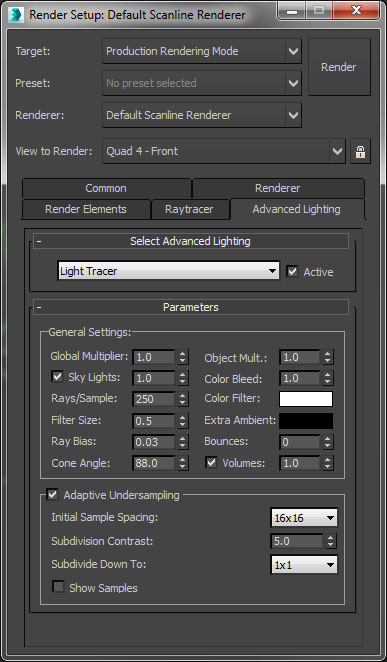
This setup gave a lovely soft look feel to the animation whilst render times for rendering the 3-minute duration were achievable in a short time frame producing a sequence of shots that have a consistent pleasing result without worrying about Global Illumination flickering problems needing to be fixed after a night of machinery being left to process 20-30 seconds of animation. It was rendered at 720p 25fps to make data sets of rendered image sequences more quickly managed, checked and edited together with avoiding the longer rendering times associated with 1080p production increasing the speed of production for the tight time frame required.
There needed to be a quick eye-catching intro animation which introduced the EncryptionBox logo (supplied to us in 2D form). The logo came to view from a vanishing point in the middle of the screen with 3D security related objects flying back round the sides of the camera.
Particle Flow 3ds max Tutorial
At various points in the video, the transition of data is shown by the flying streams of 1s and 0s. this was achieved by use of the pf flow 3ds max system as described in this particle flow 3ds max tutorial.
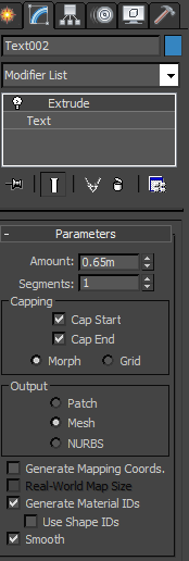
1s and 0s were created with standard 3ds max text splines. Then an extrude modifier applied.
The 1 and 0 were grouped so they could be used as geometry for the pf flow particle system.
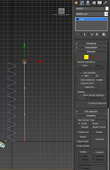
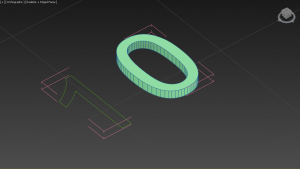
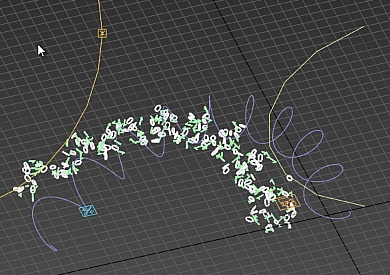
Next, a helix was made that would act as a path for the particles to flow along and next to it a line the same length as the helix was made next to it.
The line on the right was bent into curve. The helix was selected and a path constraint modifier was applied and the now curved line was selected as the path to be deformed by.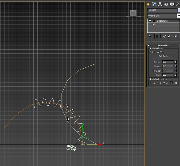
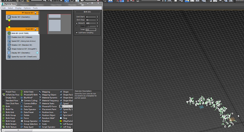
At pf flow particle system was created in the Particle Systems drop down part of the Create tab of the command panel.
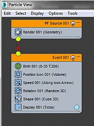
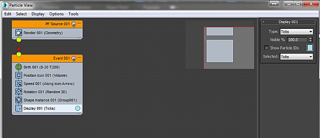
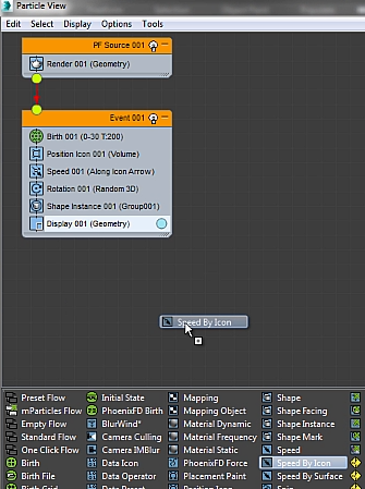
pf flow shows this configuration in Particle View when 1st made.
The 1 and 0 group was then there to be used as Geometry for the Particle flow to generate and flow by dragging the Shape Instance on top of the Shape 001 (Cube 3D) event in Particle View………
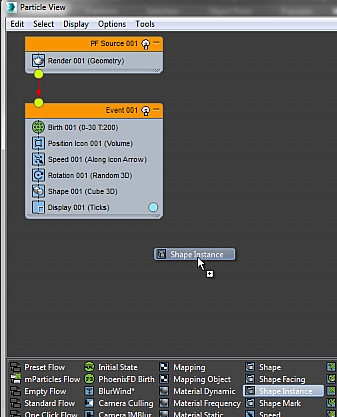
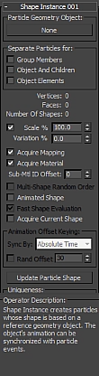
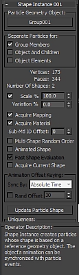
……then we the resultant Shape Instance 001 is selected in Particle View in the roll down Group Members should be ticked and the None button on the Particle Geometry Object clicked and the group containing the extruded 1 and 0 selected….
Next select the Display 001 (Ticks) part of Event 001 and on the Display 001 roll-out change Type from ticks to geometry.
A speed by icon should be dragged onto the end of the Event 001 list.
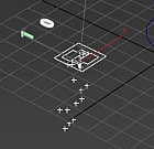
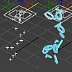
The Speed by Icon appears in the viewport under the helix: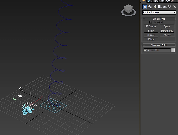
The Speed by Icon’s size is reduced for ease of seeing what is going on.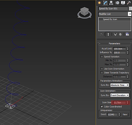
With the Speed by Icon selected switch to the motion tab of the Command Panel then select the Position Transform on the Assign Controller rollout then press the Assign Controller button above it. In the resulting Assign Controller dialogue box then choose the Path Constraint. While still on the Motion tab of the command panel scroll down to the Path Parameters rollout and press the Add Path button and select the helix.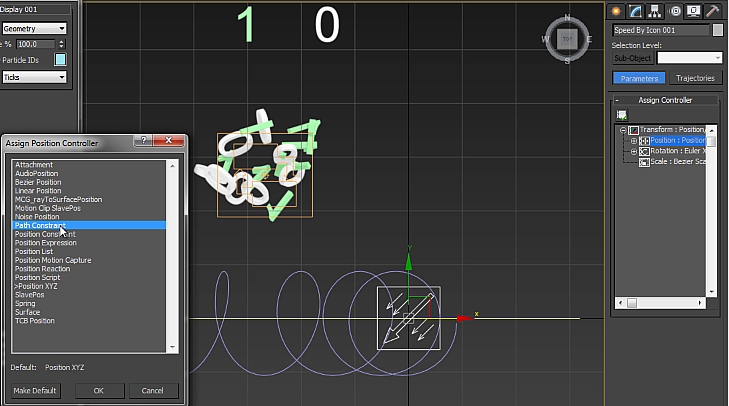
The result is that the Speed by Icon follows the helix as a path when the play button is pressed and so do the pf flow 1s and 0s but offset by the distance from the start of the helix to the pf flow icon.
To give a better look the Birth event in Particle View is altered so that the Emit Start is at frame 0 and the Emit Stop is at frame 90 and the Amount is made to be 600 so it is optimized to show off the constituent parts of the stream and the overall helical shape.